



























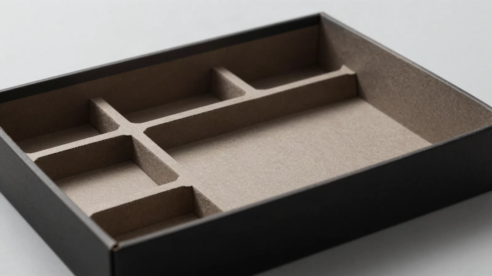

















































A die cut foam insert is a shaped interior component that holds a product in a defined position inside its package. The cutout has to match the product, the outer box, the lid clearance, and the way a person removes the item. Look at custom foam box inserts, jewelry boxes with inserts, custom rigid boxes with inserts, and custom die-cut boxes as catalog references. For logo-led outer packaging, see custom boxes with logo.
What should a die cut foam insert hold?
The cavity map must account for the product, every accessory, and the hand that removes each piece. A cavity map is a drawing that shows each opening, its position, its depth, and the space left around it. List the product, card, cable, cap, tool, or sample that belongs in the package, then mark orientation, contact points, loading order, and the surfaces that stay visible when the lid or sleeve closes.
| Insert direction | Common package structure | Design checkpoint |
|---|---|---|
| Single cavity layer | Two-piece rigid box or folding carton | Product orientation, edge clearance, removal path |
| Multi-cavity layout | Rigid presentation box or drawer or slide box | Each item, accessory, and loading sequence |
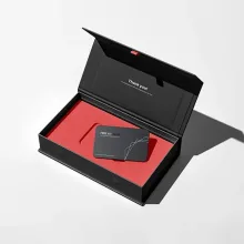
| Contour cutout | Magnetic flap or lid presentation | Product face aligned with the opening panel |
| Insert and sleeve | Printed outer sleeve around a structured inner pack | Sleeve artwork kept separate from cavity geometry |
| Insert with outer shipper | Corrugated mailer or shipping carton | Movement, void space, and outer dimensions |
How should I map cavities for a foam insert?
Top, side, and depth views expose conflicts that a top-down outline misses. Draw the actual product outline, height changes, corner shapes, accessories, labels, and surfaces that must remain visible. Mark the areas that hold the product and the areas that give fingers access. Then check the insert perimeter against the box, lid height, sleeve, and assembled closure.
The product should not rattle, but the opening cannot grip so tightly that removal damages a corner or finish. The loading order matters when several cavities share one insert. Show the first item loaded, the last item removed, and any card or cable that crosses a cavity.
Which box structure works with an insert?
Two-piece rigid boxes suit a fixed base-and-lid presentation, while magnetic flap, drawer or slide, and folding carton structures change the opening path. A straight tuck end or reverse tuck end carton can carry a lighter folding format. An auto-lock bottom changes the filling sequence, and a roll end tuck top mailer or corrugated outer box can sit around the presentation layer when the package ships.
Choose the structure with the cavity map in view. The same insert can fit the empty box and still conflict with a sleeve overlap, a magnetic flap, or the fingers needed to lift the product. Check the open package and the closed package.
What material ranges are common for insert boxes?
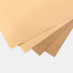
Rigid chipboard from 1.5 to 3 mm, wrapped in 100 to 157 gsm art paper, is a common presentation-box reference. SBS, C1S, or C2S paperboard in the 12 to 24 pt range is commonly considered for folding cartons and sleeves. Corrugated E, B, and C flutes can be checked for an outer handling package, with 32 ECT as a recognized board reference.
| Outer package reference | Material range | Typical use |
|---|---|---|
| Rigid box | 1.5 to 3 mm chipboard with 100 to 157 gsm art paper | Wrapped presentation shell |
| Folding carton or sleeve | 12 to 24 pt SBS, C1S, or C2S paperboard | Printed folding or sliding format |
| Corrugated shipper | E, B, or C flute, with 32 ECT as a board reference | Outer handling package |
The insert perimeter and lid clearance need a check against the selected core, board direction, and wrap. A material range is a starting reference, not a substitute for the assembled fit check.
How should an insert box be printed and finished?
Offset CMYK is a common route for detailed paperboard artwork, digital printing can suit a short run or version test, and flexographic printing is commonly considered for corrugated outer packaging. Matte or gloss lamination, soft-touch, spot UV, foil stamping, embossing, and debossing can go on the outer box or sleeve. Mark whether each effect belongs on the lid, base, sleeve, tray, or another panel.
Keep the cavity geometry separate from the print artwork, then compare the flat proof with the assembled pack. RGB art can shift when converted for press, low-resolution art can break up, and type too close to a score can fold into the wrong panel. The insert drawing should show every cavity even when the outer artwork is still being revised.
How do fit details affect a foam insert quote?
The fit starts with the assembled package's inside length x width x depth, not the empty shell alone. Include the insert perimeter, cavity depth, product height, lid clearance, card, wrap, and finger access. About 1/16 in, or 1.5 mm, is a common planning tolerance, subject to the structure and product.
Quote scope also changes with cavity geometry, foam usage, insert count, board or core, board caliper, print coverage, finishing, quantity breaks, tooling, shipping zone, and selected box structure. A single cavity has a different cutting and packing plan from a multi-cavity layout. Record the outer shipper dimensions separately when the insert sits inside a mailer or corrugated box.
What should I include in a foam insert brief?
Send enough detail to draw the product, the cavity, and the closed package in one pass.
- Provide product outlines, side views, heights, accessories, labels, and intended orientation.
- Mark cavity positions, edge clearance, finger access, loading order, lid clearance, and removal path.
- Choose rigid, folding carton, magnetic flap, drawer or slide, sleeve, mailer, or outer shipper structure.
- List the board, insert perimeter, print coverage, lamination, soft-touch, spot UV, foil, embossing, or debossing areas.
Use the product references above when deciding between an insert-led interior and a shaped outer package.
Die cut foam inserts are quoted from a 100-unit minimum. Pricing is from $0.49 per unit at volume, quoted to spec. Production is typically 8 to 10 business days after proof approval, plus delivery. Free US shipping, free design support, and a free dieline are available. Order the $19.99 sample kit; it can be credited to the first order.
Frequently Asked Questions
What are custom die cut foam inserts?
Custom die cut foam inserts are shaped interior components planned around a product outline. Each cavity needs a defined position, depth, edge clearance, product orientation, lid clearance, finger access, and removal path. The insert perimeter also has to fit the assembled box, because a cavity that works on its own can still collide with a lid, sleeve, or tray.
Should a foam cavity match the product exactly?
A foam cavity should follow the product outline closely enough to hold it, but it also needs practical clearance for loading and removal. The final opening depends on product shape, cavity depth, foam behavior, edge clearance, and the box closure. Mark contact areas and finger access in the drawing instead of guessing from a top view.
Can a foam insert go inside a folding carton?
A foam insert can sit inside a folding carton when the carton has enough cavity depth, lid clearance, and panel strength for the product and insert. Straight tuck end, reverse tuck end, and auto-lock bottom structures change the opening and filling sequence, so the insert map and folded carton should be checked together.
Why is finger access part of the cavity design?
Finger access gives the user a place to grip the product without digging into the foam or pulling against a fragile edge. A cavity map should mark the access point, opening direction, product orientation, and nearby wall clearance. The best-looking outline fails if the closed box leaves no practical way to lift the item.
How should a foam insert be checked before production?
Check the actual product inside the assembled insert and box, then close the lid, sleeve, drawer, or flap. Look for rattling, scrape points, blocked finger access, lid interference, and a cavity that hides the intended face. Review the flat drawing as well, because scores, glue areas, and sleeve overlaps can create a second fit problem.